
Add Date: 2026/1/12 Views: 17
Keywords:#MachiningCenterMaintenanceTrainingBench,#InnovativePractice,#EngineeringTrainingCenter, #CNCTraining, #CNCTeaching, #Manufacturing
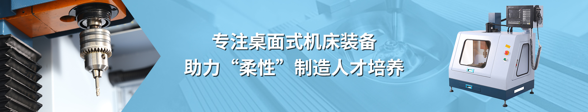
XENDOLL XD5001 Machining Center Maintenance Training Bench is developed in accordance with the requirements of the Ministry of Education's "Plan for Revitalizing 21st Century Vocational Education Curriculum Reform and Textbook Development." It is designed to meet the teaching and practical training needs of vocational education. This bench integrates multiple teaching and training projects, including mechanical processing, CNC machining center electrical control training, electrical fault diagnosis and maintenance, CNC system control principle teaching, and machining center CNC system initial parameter setting training. It is a multifunctional machining center teaching and training bench that combines CNC foundational teaching, CNC principle teaching, CNC operation training, CNC machining center electrical control teaching, and CNC machining center electrical fault analysis and maintenance. It represents a perfect combination of machining center technology and electromechanical control.
The Machining Center Fault Diagnosis and Maintenance Training Bench mainly consists of seven parts: CNC system, main electrical components, electrical control, input/output section, servo drives, machine body, and accessories.
CNC System: GSK 218MC-H industrial-grade CNC system
Main Electrical Module:
Controls the power supply of the entire training bench and provides short-circuit and overload protection.
Integrates power on/off control for servos, cooling, spindle, tool magazine, etc., with open power terminals and signal connection ports.
Monitors the operation of each control module. Indicators for spindle start/stop, servo start/stop, control system start/stop, cooling start/stop, etc., provide effective assistance for electrical circuit maintenance and fault diagnosis.
Integrates manual control switches such as CNC system key start/stop selector switch, emergency stop button, manual control selector switch, and buttons, allowing independent control of individual modules, which facilitates training and teaching for various CNC modules.
Electrical Control Module:
This module primarily displays the electrical control schematic and wiring diagram of the main electrical control. Familiarity with these is essential before practical training operations. It provides significant help for fault diagnosis and maintenance, external electrical circuit connection training, and CNC electrical control teaching.
Input/Output Signals:
The input/output control signals from the CNC system I/O interface are exposed (all signal ports such as limit switches, home position signal switches, overtravel release, cooling control signal output, spindle forward/reverse control signal output, tool magazine control signal output, lubrication signal output are fully accessible). The typical machine tool CNC system I/O interface is decomposed into multiple modules, cleverly integrating teaching and learning.
The open I/O interface facilitates diagnosis and maintenance and allows students to gain hands-on experience in electrical circuit connection training.
X, Y, Z Axis Servo Drive Module:
The X, Y, Z axis servo drive control module primarily controls the X/Y/Z axis servo motors. This module exposes all ports of the servo drive, including feedback encoder signal lines, power input/output ports, and control ports. This enables effective training on servo drive control, electrical circuit training, and electrical fault diagnosis.
Machine Body:
The machine body part adopts the Pilot brand mini CNC machining center, equipped with full servo motors, a 12-tool capacity tool magazine, an automatic lubrication system, a cooling system, a fully enclosed structure (enhanced safety), 380V power supply (convenient for teaching), small footprint, and capable of real machining operations.
Achievable Training Projects:
CNC Structure and Principles
CNC Electrical Control
CNC Connection and Debugging
CNC Fault Diagnosis and Maintenance
CNC Manual Programming and Operation
CAD and Automatic Programming
Technical Parameters:
Electrical Installation Platform Dimensions: 1200×1000mm
Controller Installation Surface Dimensions: 1200×500mm; Sturdy structure
Training Bench Dimensions: 1500×1000×1900mm
Tool Magazine Control Device: 12-station umbrella type tool magazine
Work Table: 450×160mm
X/Y/Z Axis Travel: 300 / 175 / 270mm
Spindle Motor Power: 1.5KW
Spindle Motor Speed: 24,000 rpm
Spindle Type: ISO20
Rapid Traverse Speed: 10,000 mm/min
X, Y, Z Feed Rate: 5,000 mm/min
Input Voltage: 380V
Welcome to our video link:
YouTube: Xendoll
Facebook: Xendoll
WEB:www.xendolltools.com


 Location: